
The basics of metro train running
are same as the running of main
line trains. The metro trains
need quick acceleration and the interstation
distances are small. Also the
new metro trains are provided with 3-
phase induction motors and the gear
ratio used for the metro trains are
very high.
The metro trains are for the use of
the city dwellers. The commuters
should take as little time to reach
their place of work and return home
in the least possible time. The
commuters do not carry heavy
luggage with them like the long
distance travelers. The toilet
facilities are provided only on the
platform. The doors of the metro
trains are closed while it is running.
These are some of the features of
metro trains.
ACCELERATION
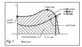
As can be seen from Fig 1, out of the
total torque, part is utilized to
overcome the load torque and
balance is available for accelerating
the motor. If the surplus torque is
more, the motor accelerates quickly.
The motor attains a balancing speed
at A when the load torque and the
motor torque are equal. Since at
point A, no surplus torque is
available, the motor will run with a
speed corresponding to slip S1.
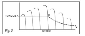
For the vvvf drive, the points on
family of torque slip curves are joined
to get a form given as A B and C in the
Fig 2 given below.
In Fig 3, A B is a constant torque
region and BC is a constant power
region. Though for the vvvf drive
motor, it is a common practice to
show the curve AB & BC as given
below, it should be kept in mind, that
the vvvf drive motor is an induction
motor and behaves like a normal
induction motor.
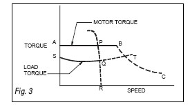
In Fig 3, when a chosen frequency
corresponds with synchronous speed
for point R, the, motor will develop a
torque corresponding to point Q. If
the frequency is increased further, the
speed will increase till it reaches point
T. The speed corresponding to point B is
the base speed and the corresponding
frequency is the base frequency. The
motor will operate most efficiently at
the point B and the motor is designed to
work at this point. BC region is like a
weak field region of dc series motor.
The speed in this region is above the
normal speed and the torque is reduced
and follows a curve BC.
It will be clear from the figure that
after point B, the accelerating or
surplus torque gets progressively
reduced. The rate of acceleration
therefore reduces.
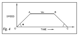
The speed with dc motor will increase
along line oA and remain stable from
point A to B after B it gets reduced due
to braking till it reaches point C. This is
the speed time curve with dc motor.
The acceleration and retardation are
tan a and tan ß respectively. This graph
gets slightly modified in vvvf control
(Fig 5).
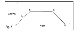
The oA corresponds to the
accelerations in constant torque region,
followed by AB in constant power
region. The rest of the curve is same as
in Fig 4. But normally instead of using
two accelerations, average acceleration
is used and a Fig 4 is used for the
calculations of various parameters in
practice even for vvvf drive.
The use of high power motor is
preferred by many people for achieving
the quick acceleration. But, the use of
optimum size of the motor should be
made to ensure minimum loss of power.
Copper loss is thus proportional to the
square of the voltage applied. Use of
high acceleration will mean use of high
P2 or high V in V/ƒ ratio.
Aiming to achieve high speed in quick
time will result into high loss of energy.
We therefore need to see whether
achieving high acceleration is necessary
to obtain the minimum possible interstation
running time.
Consider the two speed time curves
given in Fig 6.
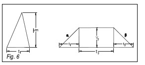
It is possible to construct the triangle
and the trapezium of the same area,
which would be the interstation
distance. If the maximum speed Vm is
high, the altitude of the triangle will be
high. The base of the triangle will be
therefore less. In the second case, the
base is more and the height of the
trapezium is less. Thus, with an
acceptable running time between the
stations, the, altitude of the trapezium
can be reduced, thereby reducing the
energy loss.
Consider a practical case of one of the
metro lines. The maximum speed is 80
kmph, the acceleration is 0.78 m/sec2
and the braking is 1 m/sec2. The
interstation distances are
approximately 1 km. The smallest
interstation distance is 596m and the
maximum is 1,432m.
The speed time curve for these two
locations is given in Fig 7
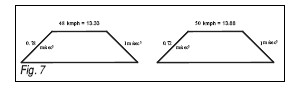
Thus it will be seen that it will not be
possible to attain a speed of 80 kmph.
The traction motor does not touch the
knee point but stops short of it. The
traction motor runs efficiently at fb &
vb, the base frequency and base voltage.
At the lower speeds, the motor will
operate at high slips and hence, will
result into greater loss. It is therefore,
desirable to have motor of proper rating
to ensure minimum loss. If a bigger size
of the motor is selected, apart from the
motor running inefficiently, the size of
the transformer in the motor coach will
be more and also the size of the traction
transformer in the substation will be
more. This too will result into more
loss. The metro systems, if motor size is
not properly selected, it will result into
loss of energy and will ultimately lead to
leakage of revenue.
USE OF HIGH GEAR RATIO
The high gear ratio will result into
higher acceleration as the torque will
increase at the cost of the speed. This is
advantageous at start but the balancing
speed is achieved at higher value of
voltage in the V/ƒ ratio. Since the
copper loss will go up with higher
voltage, the use of optimum gear ratio
will minimize the loss of energy.
Conclusion: There is a tendency to use
bigger size of traction motors for quick
acceleration. Similarly to increase the
starting torque, higher gear ratios are
employed. There is a limit to which
higher sizes can help. The use of bigger
size of the motor results into higher
capital and running costs of metro
trains. Therefore, the traction motor
and a gear ratio of correct size should be
chosen for the metro applications.
(S.P. Khade is Director-Technical,
Mumbai Metropolitan Region
Development Authority)